
Bias Questions 410HD 130 Tube Phase Inverter
Greetings. I picked up this early 4x10 combo from a guitar shop in La Mesa, CA over the summer and played the hell out of it. Sounds pretty good but the reverb is weak and I figured it could use a maintenance stop.
The amp looks like it has seen little work. There is a note taped inside from a tech back in the early 90s saying they replaced the ot and the power tubes. The current tubes are JJs that don’t look that old. The chassis is very dusty inside too.
So I replaced all the electrolytic caps, the 10 ohm bias resistors, and got ready to set the bias and got stuck.
It appears I have one of the older models with the tube phase inverter.
What is confusing me is the 10 ohm resistors are wired in parallel giving me 5 ohms to ground from all 4 pin 8s. That is all the pin 8s are linked by three gray wires. The schematic I see shows a Y dot at all the cathodes then the 1/2 volt measurement down below as is well discussed here.
It seems to me that if all the y dots were linked by wire the two resistors should be in parallel and 5 ohms is correct. But that seems strange to me especially if they want 1/2 volt across it.
I also have this green wire jumping across the bias resistors running pins 8,1 and 2 directly to ground and I do not think that is factory. Anybody have any ideas about that?
So before change the bias setting can somone please confirm if the 10 ohm resistors should be in parallel and I should be looking for 1/2 volt across it or should I be looking for coming else like 1 volt?
Thanks in advance.
I have a bunch more questions once I get the bias sorted.
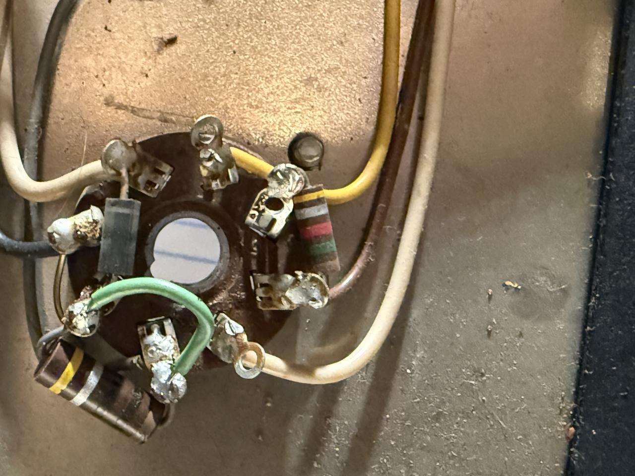
Why they bypassed the 10 ohm…
Why they bypassed the 10 ohm resistors is anybody guess. personally, I would add 1 ohm precision resistors from each cathode to ground to allow you to measure EACH tube separately.. That crap of 1/2v at "Y" was only good when tubes were good. The 1 ohm resistors allow individual measuring and that way you can set the HOTTEST tube to around 22-23mA (measure mV) and be safe.
Thank you for your comment. …
In reply to Why they bypassed the 10 ohm… by mm210
Thank you for your comment. So 1 ohm in series in each with a 22/23 mv reading on each. If the 10ohms were in series at 5 ohms net and 1/2v to ground does that get close to the 22/23 mv? In other words is it taking the same measurement a different way? Thanks.
Kind of. THe 1 ohm resistor…
In reply to Thank you for your comment. … by Scowman
Kind of. THe 1 ohm resistor allow measurement of EACH tube separately instead of the COMBINED current draw of the tube sets. 1/2V equates to 50mv per pair, which should be 25mA per tube but one could be 30, the other 20 so too hot and too cold. That's why the individual 1 ohm.