RD-50 Head restoration / Effects Loop help
Hi, 2nd post here and I wasn't certain which sub forum to start this thread but this seemed like the spot. Not exactly Urgent though with 'C-19' eliminating all of our gigs indefinitely...:-( Anyway, I just bought a 1982 RD-50 head. The amp works and the clean channel sounds nice. The limiter channel however has been heavily modded, replacing the treble and bass pots with 3 position,multi capacitor switches, one labeled 'brilliance' and one 'cut'. Also an additional 'gain' pot has been installed on the rear panel. These do work though! However, an effects loop has been added to the rear panel and it results in screeching feedback if anything is inserted in the loop.
I noticed R62 is looking toasty and read here that replacing d9 is a good idea.Replaced R62 and ordered a 1n4751a zener. All the electrolytics are original so I just ordered a full replacement set.
Right now, all I need to do is get a gig-worthy effects loop happening since the chassis has already been drilled
There are more things to address, but I will start here. First will be replacing the electros and D9 but they won't be here for a while so nothing urgent here!
Thanks in advance if anybody has the time to guide me through this!
I'm in Europe so sending it to Ed Goforth is not an option. Plus the cancelation of our tour means money IS an object ;-)
Member for
5 years 9 monthsMember for
5 years 9 monthsMember for
5 years 9 monthsMember for
5 years 9 monthsOk, now I'm screwed :-(
Well, I went ahead and recapped all the electrolytics. I decided to just remove the loop as it was just two wires tacked on to the bottom of two components on the board, and a ground wire to the ground lug. There are no cut traces or anything weird like that. Anyway, I fired the amp up and no sound from the input. The tubes are glowing and all solder joints look good and show continuity. ALL wires are securely connected.There are no damaged traces and continuity looks solid. The problem is I don't remember exactly where the guy had the two wires for the loop tacked on. Not that I want to put the loop back anyway, it was pure screeching feedback. I should have been able to just remove the loop right? Now I'm bumping this thread for urgent status.... :-(
Member for
5 years 9 monthsMember for
11 years 10 monthsStart with the basics
I'm guessing you didn't take any photos of how the FX loop was installed before removing it? I've done that...once.
First, double check all your new caps are installed correctly - polarity, no stray solder blobs or bridges, etc. All grounds intact?
If that all checks out, I'll bet the main output was connected through the FX loop output, so that when you disconnected it, you broke the connection to the main speaker out. Do you have an audio probe to see where the output is failing? If not, you can easily make one using the video from Billm Audio as a guide:
https://www.youtube.com/watch?v=IEcyDzYAsuU
Of course, I could be completely wrong, but that is where I would start.
Good luck.
Member for
5 years 9 monthscaps good
Thank you for the reply. That sounds exactly like what's going on because it doesn't make a sound, completely silent. No fuses blowing,tubes are glowing and its powering up fine...The cap polarity,grounds and solder joints all check out fine. I may not be knowledgeable like a tech and my schematic reading is paint by numbers good, but 30 years of soldering weekly and my soldering skills are outstanding. Unfortunately, removal of the loop killed the amp....:-(
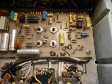
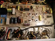
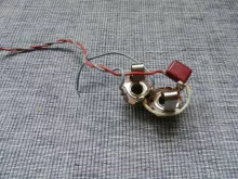
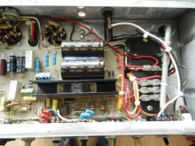
Heres the loop that I removed, not that that helps. I'm pretty certain it was connected to R34 and the white wire that goes to the center lug of the Reverb pot. But I'm not sure which wire goes to which lug and I don't want to guess. There were only 2 wires going out from the loop to the underside of the pcb. Nothing from the loop to the speaker or line out jacks.
I've never used an audio probe but looks like I will have to. Thanks for the link, BillM sure was a great guy and is truly missed by the diy guitar community.
https://drtube.com/schematics/musicman/rd50a.gif
http://www.pacair.com/mmamps/schematics/Musicman%20RD50a%20layout%202.p…
Member for
5 years 9 monthsFIXED!!!
Ok, my eyes aren't what they used to be. There WAS a cut trace between the 22K r16 and the .47 C41. Bridged that by installing a new 22K and using its long leg to wrap around C41. Loop removed and its working great!
Now, two final questions:
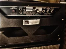
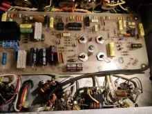
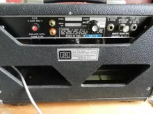
1] I have two holes on the back panel. I'm thinking of adding two RCA jacks and somehow connecting them to the two RCA footswitch jacks.[they are the two RCA jacks on the left in the attached image]. It would be better to have them accessible on the back panel than unreachable underneath the chassis where the are in stock configuration. Any suggestions on the proper way to do this?
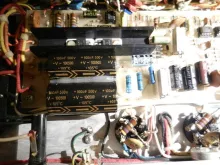
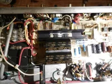
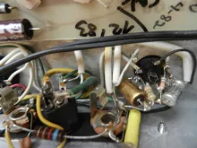
2] Looking at the 12x7 socket, it looks like a mess! Any idea whats going on there? I'd like to clean that up but it appears to have extra caps and resistors. Should I just leave it like this [it works fine] or would you suggest rewiring it? This is an amp I will use live and reliability is of utmost importance!
Thanks you guys, this is an amazing website!!!! :-)
Member for
5 years 9 monthsMember for
5 years 9 monthsMember for
5 years 9 monthsMember for
5 years 9 monthsMember for
11 years 10 monthsYou've been busy!
First, congrats on finding the problem and solving it.
I was going to suggest you leave the footswitch RCA jacks where they are, because how many times do you really need to unplug your footswitch? But since you've already gone ahead...
Did the footswitch control Reverb before you moved the jacks? If so...
The FS1 jack on the board controls the Reverb. The sleeve or shell or body is grounded to the chassis, as are all the FS jack shells. The tips are not grounded. Reverb is normally on in the default ungrounded state, that is, the tip and shell are not connected. When grounded (tip connected to shell), Reverb is off.
Is the new rear FS1 jack shell grounded, that is, physically connected to the chassis?
Are both the the orange wire and bent metal wire that were soldered to the original FS1 jack tip now soldered to the new FS1 jack tip?
If so, assuming a good tank and cables, Reverb should be on. When you connect the tip to the grounded shell, Reverb should shut off. The footswitch opens and closes this connection, unless it has a short or open internally.
As for the extra components on your 12AX7 socket: that may be a modification to improve the notoriously bad stock Limiter/OD circuit. If you can list component values and how they are connected, I can confirm what you've got. Most likely it's the Bob W mod or a variant, to make the Limiter side sound like a very good Blues Breaker overdrive pedal to my ears.
Member for
5 years 9 monthsHey Inertian,about the mod.
I'm not sure what the Bob W mod is but the mod on my RD-50 is unlike anything I've seen before. Like I said, two three position switches with various cap values replace the Limiter treble and bass pots [the cap values have been sharpie'd out so its a secret],and a rear pot that very smoothly affects the distortion along with the stock gain pot! But thats not all..... There are two extra caps and a resistor under the board connected to IC 1 and going to the 12ax7, which also has extra caps and resistors. No clue whats going on with this mod but it actually functions and doesn't sound that bad. If the stock Limiter channel is ''notoriously bad'' maybe I should leave this mod in place? I'm afraid that undoing the mod might be a can of worms that I just shouldn't open. :-D Maybe I should keep a look out for a stock RD50 1x10 or 1x12 combo at a good price so I can compare the two.
If I have any complaint about the mod, its just a bit muddy compared to the bright and pristine clean channel. I'm considering maybe a small value 'bright' cap across the limiter volume pot maybe? But for now, pedals and clean channel are sounding phenominal.
Member for
5 years 9 monthsfs1 jack
Inertian, great reply! Heres how I wired the new FS1 jacks. Both have a single shielded wire going back to the original fs1 jacks, tip to tip. I grounded the shield on one end to the ground lug in the center of the four original fs1 jacks, and heat shrinked the shield on the new jack end. You asked: ''Are both the the orange wire and bent metal wire that were soldered to the original FS1 jack tip now soldered to the new FS1 jack tip?'' The answer is I didn't move them from their original location, only added a wire from that same spot over to the new RCA jack tip. Both of the shells of the new RCA jacks have ground rings. I ran a solid core wire through both ground rings and terminated it at the nearby chassis ground lug. So it should be wired the same as the original fs-1's??
That is, the new shells are both grounded and each tip has its own wire to the tip of the original fs-1 lug. It made sense to me but obviously something is not right. The switch changes channels and lights up, but there is no reverb on or off. Reverb works when the footswitch is disconnected.
As for why I went this route, I think its a hassle having the switch crammed into such a tight space for transport, and probably a potential hazard for the tubes. Also, it looks kinda nice, not an eyesore like two empty holes. [By the way, these holes are only drilled through the faceplate,through a rectangular cut-out in the chassis where another rocker switch goes in U.S models.] Now the 'drive' pot on the rear is another story, and its placement was definitely not well thought out. I'm glad the loop is gone, but now I need to get the switch working!
Thanks a million for your assistance!
Member for
11 years 10 monthsOK, try this...
With footswitch disconnected, make a connection between the tip and shell of the old FS1, and see if the Reverb turns off. Now try the same thing at the new FS1 jack. Both work the same way? If so, your wiring is fine, but you have an issue with your foot switch.
If the original FS1 location works correctly, but the new FS1 location doesn't, there is a wiring issue between them.
Member for
5 years 9 monthsThx!
Going on a camping trip for a week and the amp is back in its shell. I'll try that out when I get back and let you know.
Played the amp for a couple hours today and its just so inspiring, best clean tone I've ever had and sings with overdrive and distortion. Quiet as a mouse too with the exception of a bit of reverb buzz. Ordered a MOD tank today too!
Member for
11 years 10 monthsReverb Buzz
Tough to eliminate reverb buzz, especially in a head cabinet where the tank's output transducer is even closer to the power transformer. You can try rotating the tank 180 degrees, or moving it around in the cab (as much as you can) to see where it has the least amount of hum. Good shielded reverb cables help too.
Member for
5 years 9 monthsa-ok!
Alright, I had a bad RCA jack on the rear panel. I decided to put 1/4'' jacks there so I can use a single fender footswitch for the reverb only. The RCA jacks underneath are still operational. However, there's a pretty loud 'pop' when changing channels. Reverb switches silently. Probably has something to do with the limiter channel mod but in case its not,is there anything I can look for to reduce this? Or any components in the footswitch path that should be changed? I did install a new CD4066BE in IC 2 for the footswitch, but it didn't effect the 'popping'. It 'pops' with or without my new wires to the rear panel installed. Otherwise the amp is working and sounding great! My mod tank and nice short, shielded RCA cable aren't here yet but re-orienting the tank helped a bit with the reverb buzz. Also, changing IC 3 to an LF353 helped a bit more. I just realized it buzzes with no reverb tank hooked up too, louder as the reverb pot is turned up.
Thanks for the replies and for your time! Great website and a GREAT sounding amp!
Member for
11 years 10 monthsMember for
5 years 9 monthsMember for
11 years 10 monthsMember for
5 years 9 months'pop'
Well, got her all buttoned up after changing the .1 ceramic caps and the footswitch still pops when changing channels. Reverb switches silently.
In trying to figure out where its coming from I realized it didn't pop [or I didn't notice it] before I changed the electrolytic caps [all]. Is there any electro that's in the footswitch signal chain that I should look at? I've never had a faulty or leaky brand new cap but I suppose it could happen... Double checked all soldering and connections and they are fine. The amp is running quietly and sounds great.
And lastly, eventually I would like to wire up the stock tone and bass potentiometers on the Limiter channel and un-install the modification that was done .[ The mod doesn't sound bad but its kind of muddy without a tone control and seems to be geared towards high gain, something I'd rather use a pedal for]. However, my schematic reading isn't at the level that I can decipher where each pot wire goes to the circuit board. If any of you get an RD-50 in for service or on your bench I would love a photo or two of the limiter channel tone and bass pots and how they are connected to the board.
No rush on this but it is on my future wish list of things I would like to do!
See post #15 about the modification.
Member for
11 years 10 monthsFootswitch?
Is it only when the foot switch is used to change channels? Does the channel switch on the amp pop? Just fishing for more clues. BTW: The Reverb switch is quiet because its function is to ground or un-ground the reverb signal output. It doesn't switch any DC voltages on and off like the Channel switch does.
Member for
5 years 9 monthsfootswitch
Yes, its only the channel switch. And yes, the front panel rocker switch has a little pop to it also, but not as loud.
Played the amp for a couple hours today and the modded channel actually sounds quite good. So being able to footswitch between channels quietly would be great!
Member for
11 years 10 monthsMember for
5 years 9 monthsMember for
11 years 10 monthsMore De-Coupling aka More Cow Bell
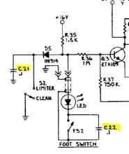
The pops are caused by a transient voltage spike that happens when the channel switches are flipped. The job of C21 and C22 is to shunt those transient spikes to ground before they get onto the +/- 8V and +/-16V lines. Perhaps more de-coupling is needed. If this were my amp, I'd temporarily install an additional .1uF cap from the junction of Q3 Base, R36 and R37 to ground to see if that will quiet things down. If you check the RD65 schematic, they do have additional .1uF caps (C44 C45), the difference being the RD 50 uses 2 transistors to control the cmos switch and the RD65 uses a pair of Op-Amps (IC-6) for the same job. Feel free to ignore this advice if we're going too far out on a limb. I'm also hoping that Lars (lmv) will chime in as he has more hands on experience with the RD50 amps and may have additional insights and information.
Member for
5 years 9 monthsDon't fear the reaper...
Good advice, I ordered some of those transistors and was going to try swapping them out, but they won't be here any time soon. Your idea sounds legit, but I'm having trouble with this:
''install an additional .1uF cap from the junction of Q3 Base, R36 and R37 to ground''.
It sounds like 3 points that you want the cap to and the other end to ground? Do the Q3 base,R36 and R37 all meet at one location?
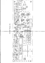
If you look at the layout diagram, is there a spot I could tack one end of the cap to on the top side of the pcb and the run the other end to a ground point?
Member for
11 years 10 monthsLook near the PCB Date
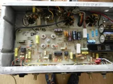
Go up to entry #3 and look at the 2nd pic. It has the 4 reverb tank and foot switch jacks and the date 8-4-82. The switch control circuit is on left of the jacks and above the large electrolytic cap. If my eyes were better I'd trace the circuit from the pic. Use your ohm meter and go from the jack to other side of R36 1M resistor. That's where to tack one end of the cap. Look at the big electrolytic cap at the bottom. There are 2 ceramic caps and a zener diode right above. This appears to be ground. Use an ohm meter to verify that point is ground. If it is, tack the other end of the cap to the left side of the zener diode. Let me know if it helps or worse or no difference.
Member for
5 years 9 monthsMember for
5 years 9 monthsstill popping
Ok, I tacked a .1 cap onto the ground side of D10 to the side of R36 away from the RCA jacks and its still popping. Any other suggestions welcome! I have 2 bc550's coming to replace the Q3/Q4 ztx109 transistors but its just a hunch/long shot.
The popping isn't too bad as long as the reverb is not engaged, but its very loud if the spring is active.
Oh, replaced the reverb tank with a very nice MOD / MOX 8BB2A1B and made some very nice RCA cables. This along with flipping the tank 180 degrees made the reverb almost silent, so that was successful ! :-)
https://www.ebay.com/itm/NEW-Reverb-Tank-MOX-8BB2A1B-equivalent-to-MOD-…
Member for
11 years 10 monthsMight this be related to "Shutdown Squawk?
czech-one-2, does your amp pop or "sqwawk" when you power it off?
Like some other RD50 owners have posted, my '82 110 RD50 "squawks" when powering the amp off while on the Clean setting. Dead silent when powering off in Limiter mode. Amp has been completely recapped, sockets cleaned, etc. Bleeder resistors measure in spec. Hmmm...
Member for
5 years 9 monthsMember for
5 years 9 monthsMember for
5 years 9 monthsfootswitch silent, yay!
Ok, it was just a hunch but I changed the ztx109 transistors [Q4 / Q3] in the footswitch path with BC550C transistors and the limiter channel footswitch is absolutely silent,as well as the front panel rocker switch! Just FYI, THE BC550C / ZTX109 ARE THE SAME PIN OUT! I was under the assumption that I had to flip them 180 degrees but no, they are the same collector/emitter pin out. Wish I knew this going in but I learned the stupid way....


images
board