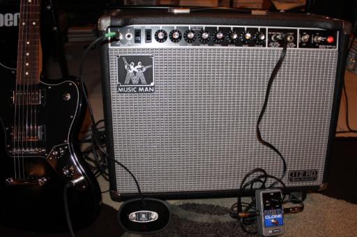
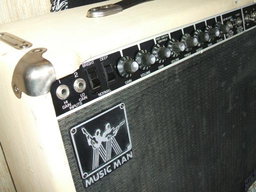
weird switching issue between clean & limiter channels 112 RD50
I just bought an RD112 50 made in Dec 1980 and thanks for letting me join the group. What a great resource!
My new amp sounds awesome with a celestion Neo creamback ( and lightweight too !)
problem is that the clean/limit switch does not appear to be working correctly.
the only way i can get the Limiter channel to work is if i have the rocker switch ( on front panel) in the limiter position BEFORE i turn the amp on.
If i then press the limit/clean rocker switch to clean position it makes a loud scratch noise, switches to clean but now stays there - if i try and switch back to limiter it doesn't work. ( power off, switch to limiter, power back on again in order to get back to limiter channel)
tried a footswitch ( old fender style with RCA adaptor) and could not switch either way..
any ideas?
many thanks for your help!!
Member for
11 years 3 monthsMember for
7 years 10 monthsMusic Man 112RD sixty-five
Two OLP MM4 Silhouettes with Lace Sensors
Member for
7 years 9 monthsRD50 switching
I had a related issue with my 110 RD fifty. The RD50 doesn’t use relays to switch channels; it used LDRs (Light dependent resistors). These had worn out on mine and were causing spontaneous channel changing. The Music Man RD foot switch is not the same as the Fender so the Fender one may not be compatible with the LDR circuit. It is an inexpensive fix to replace the LDRs. A simpler issue would be if IC2 has failed. It controls the switching. It is a 4016B, if I remember correctly. It’s pretty cheap.
Member for
11 years 9 monthsMusic Man 112RD sixty-five
Two OLP MM4 Silhouettes with Lace Sensors
Member for
7 years 9 monthsLDR
I don’t mean to contradict you but according to the tech who worked on my 110 RD fifty there were two he replaced. From what I can gather, both Music Man and Mesa Boogie used LDRs to allow for silent channel switching. I’ll ask him again, to be sure, when I send my newly-purchased 112RD sixty-five to him for inspection. Regarding the original post, does the Limiter Switch on the amp have to be in the clean position for the foot switch to change channels?
Member for
7 years 10 monthsMember for
11 years 9 monthsSwitch
Hello again,
There are no LDRs in the RD-1650 switching circuit. Whoever told you that is somehow misinformed. I cannot tell of course what is in your particular specimen of the amplifier, but the stock circuit does not use them. LRDs were used in the RP series and the later 2 channel MM amps in the phasØr circuit. It may be that your tech was referring to the two NPN transistors used between the foot switch (and the front panel switch) and the 4016B chip.
The foot switch is a simple make/break switch but the distortion switch circuit allows for an indicator LED to be used when the switch is 'make'. The front panel switch has a single diode in series that clamps the voltage of the R35/36 junction at 0.6V when in 'limiter' position, overriding whatever the foot switch is doing. A problem with either of the two transistors Q3 and Q4 or, as mentioned earlier, the 4016B chip can cause unexpected switching behaviour. Diodes D1 through D4 should also be inspected as a problem in either of these could cause stability issues in the switching.
Sincerely,
Lars Verholt
Member for
11 years 9 monthsMy RD-100 uses an IC!
I know my RD-100 uses an IC 4016 to switch channels, and the schematics show the RD-1650 circuit using the same chip. I built a switch for mine with an inline LED on the "channel" circuit like the original. (Reverb switch has no voltage available for an LED).
http://www.pacair.com/mmamps3/sites/default/files/docs/1650-rd.pdf


Bad Switch
Crack it open...and post pictures. Sounds like maybe a short in the switch?